PUBLIC LANDSCAPE · WORKING INFRASTRUCTURE
A clearer architecture.
A credible next step.
Five diagrams explain how the park, the submerged halls, and the river relate. The model now tests a quieter material palette, finer planting, lower landscape folds, and watertight end caissons. These drawings make the proposal’s construction logic and remaining questions explicit.
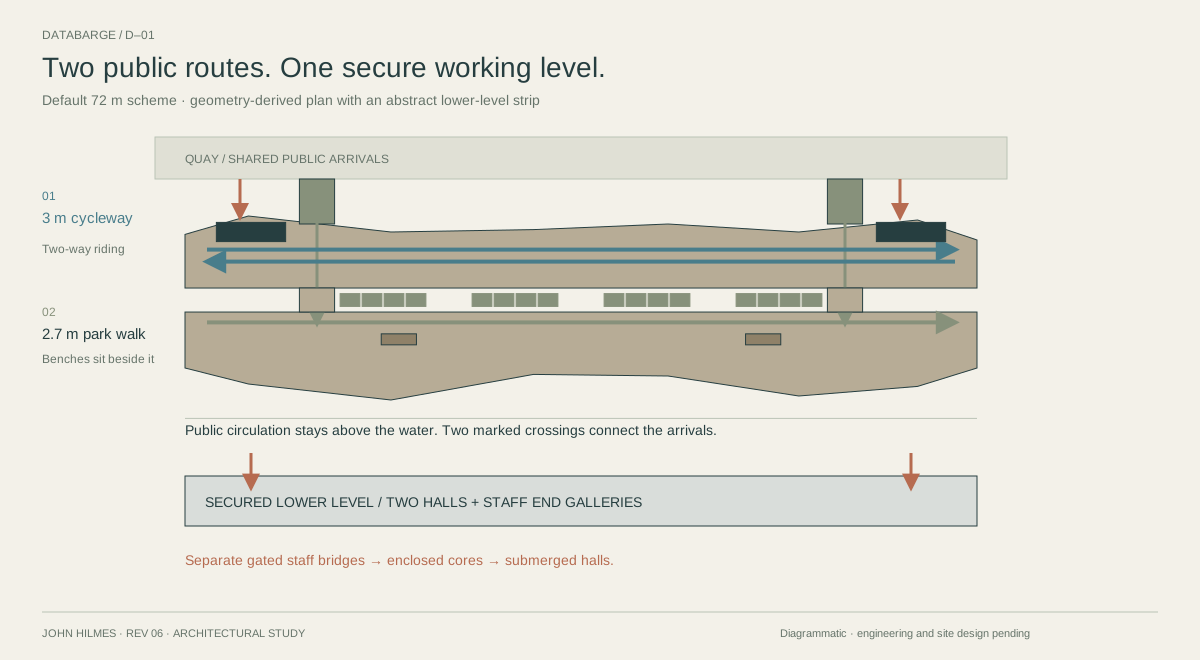
01 / Circulation. Keep through-cycling on the quay side and strolling on the river side. Two shared arrival gangways meet marked crossings; the staff gates and enclosed cores remain separate.
Download SVG ↓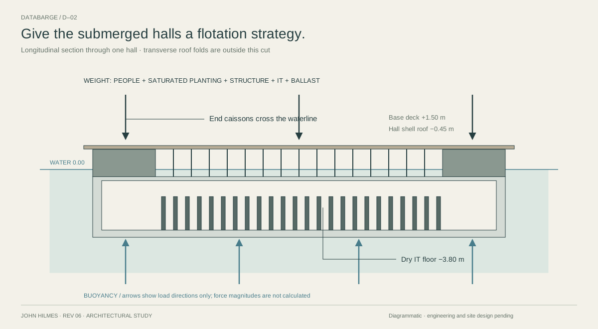
02 / Flotation and support. Four end caissons extend from the submerged hull roofs to below the public deck. They introduce waterplane area and volume above the nominal waterline. Weight, ballast, draft, stability and damaged-compartment behavior remain uncalculated. The arrows express a load path, not balanced forces.
Download SVG ↓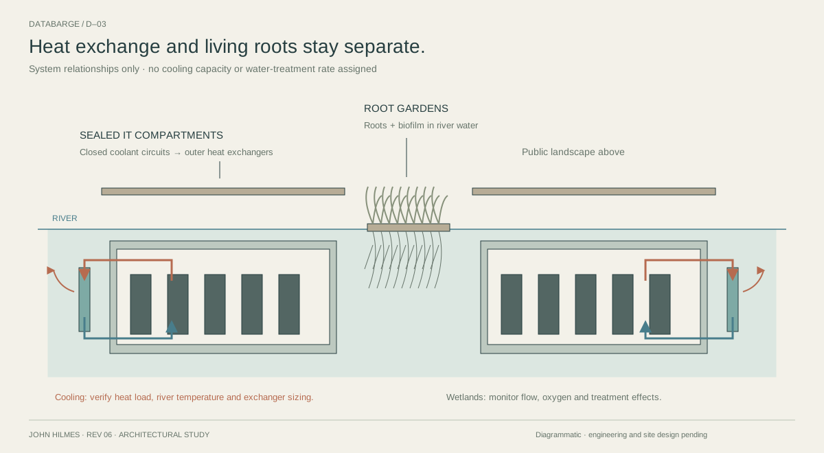
03 / Water and heat. Dry IT compartments exchange heat through a separate coolant circuit. Root gardens contact the river in the central slot. Their physical separation is shown; thermal plumes, fouling, oxygen and ecological performance still need study.
Download SVG ↓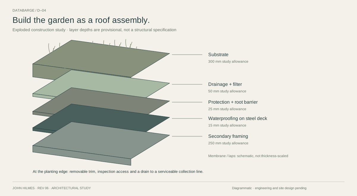
04 / Planted roof assembly. Replace the idea of a green surface with a maintainable assembly. The 300 mm planting-medium allowance is a starting assumption; planting selection and saturated weight must determine the final depth. Drainage runs to inspectable collection, separate from the floating root gardens.
Download SVG ↓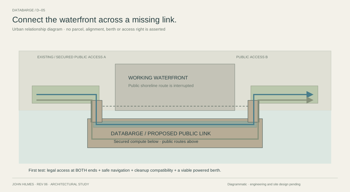
05 / A missing waterfront link. The NYC investment case starts with two legally accessible public endpoints. A floating segment could connect them while preserving working-waterfront and navigation requirements. This is an urban relationship diagram, not a selected parcel or approved alignment.
Download SVG ↓What makes this real next?
| Choose the berth | A surveyed quay, river depths, water-level range, current, navigation envelope, power and fiber connection points. |
|---|---|
| Close the weight budget | Steel, IT equipment, saturated planting, people, utilities and ballast; then displacement, draft, center of gravity and intact/damage stability. The park’s soil and crowd loads belong in the first calculation. |
| Test one working bay | Assign an actual IT load to a 12 m module. Size its cooling circuit, test it against seasonal river temperatures, and establish cleaning and replacement access. |
| Resolve safe operation | Protected egress, watertight boundaries and penetrations, fire separation, ventilation, rack replacement routes, moorings, and gangway movement. |
| Prototype the public edge | Build a bench / guard / planter / drain assembly at full scale. Test comfort, maintenance access, slip resistance, lighting and replaceability. |
Sources informing the technical questions: WBDG on vegetative roof layers and wet weight; DNV on lightweight monitoring, nearshore mooring and novel-concept assessment. These are reference topics, not a determination of the project’s applicable rules. Full archive, precedents and design notes ↗