A public river.
A working machine.
The new DataBarge treats the original civic bargain as the project’s organizing idea: private computation occupies a public resource, and its architecture must give something spatially useful back. The 2026 proposal turns the earlier fragments into a complete, inspectable floating building.
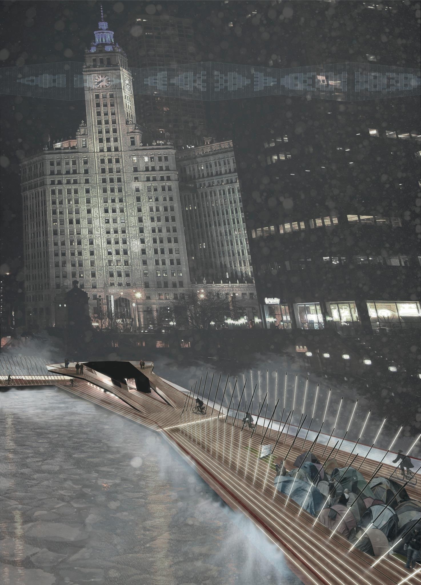
The city is the protagonist.
The original DataBarge project text described how servers below deck discharge excess heat to the river, while cyclists receive a floating highway above. That is the original proposal’s description, not an engineering claim for this version.
The larger image from the original archive makes the social program clearer: people cycle, pause under angular shelter, and occupy the deck with tents. Its timber surface, folded geometry, tilted lighting masts, and relationship to Chicago’s river edge are carried forward as architectural references.
The October 2012 #occupytheriver post connects this river project to civic participation and public occupation. The original STUDIO FALL 2012.mindnode file contains research on transience and permanence, hidden infrastructure, graft, social networks, and slowness. One branch asks who the protagonist is and answers: the city.
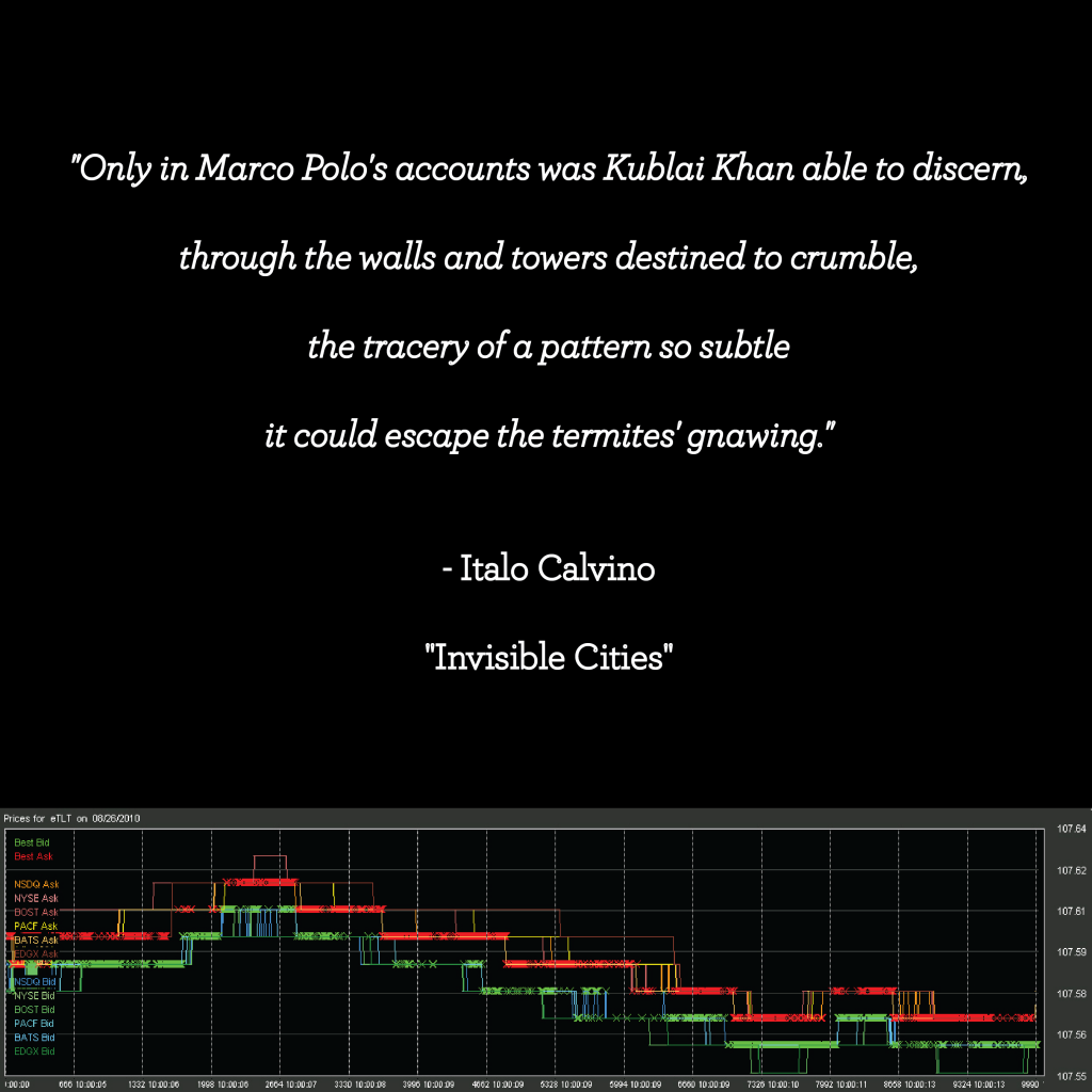
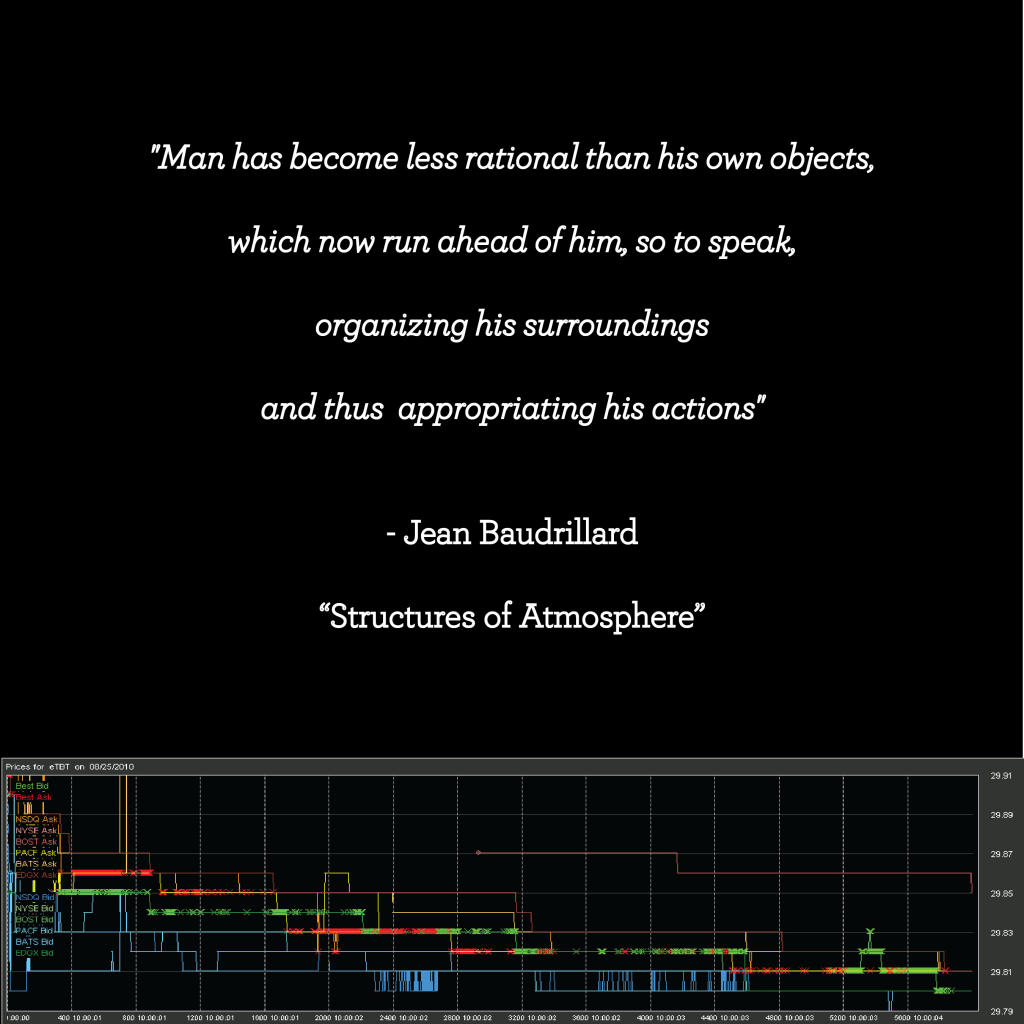
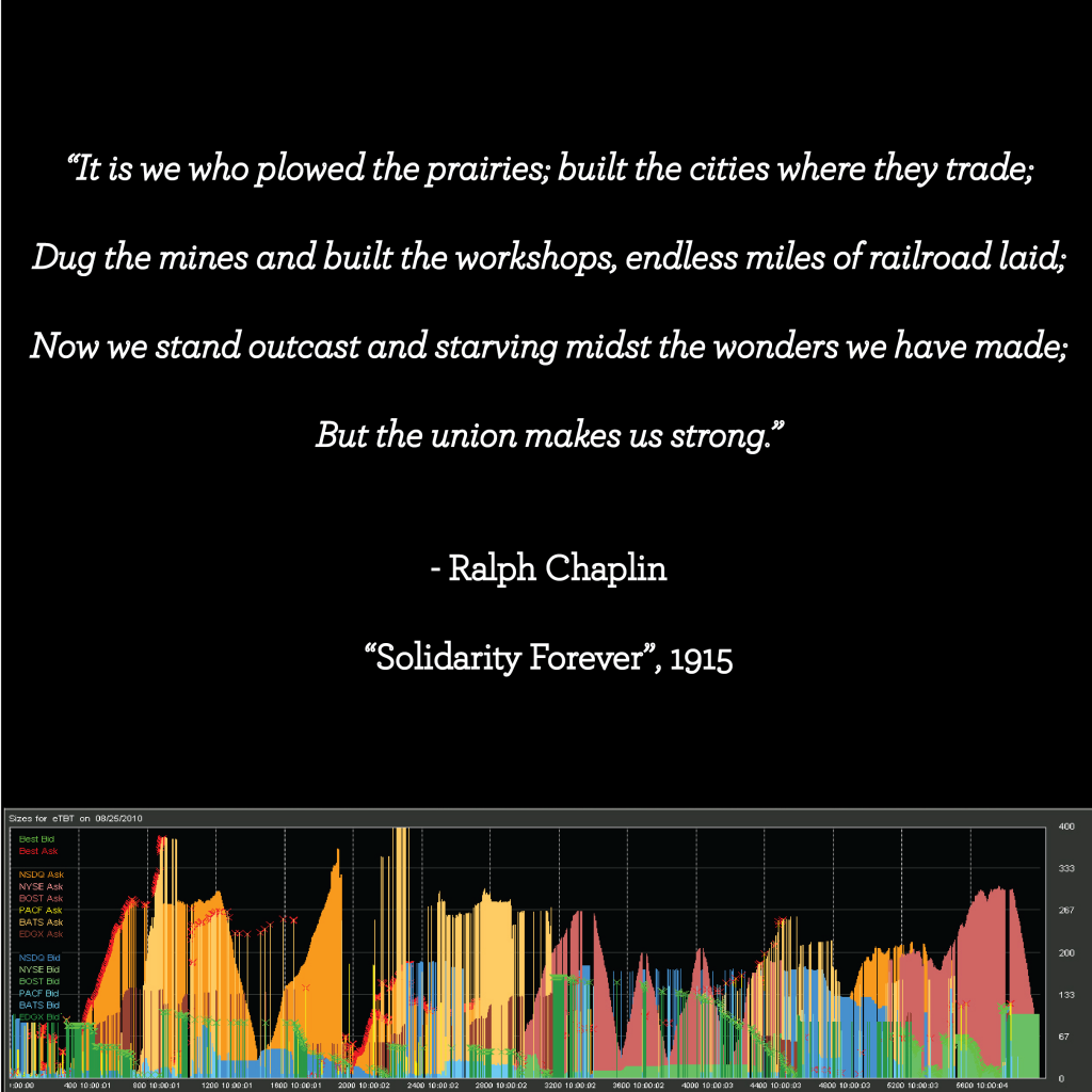
The studio mind map is contextual evidence. It does not contain a dimensioned DataBarge plan. Its quoted reading excerpts are not all statements authored by John.
From the graduate archive.
The original River Run image, studio notes and theory panels inform this new interpretation. No native DataBarge model has been positively identified; the 2026 geometry is newly authored.

What the Japanese proposal changes.
The Marine Insight article prompted this update. The NYK consortium announcement puts the first practical configuration alongside a quay, where power, telecommunications, and physical access can be connected. It distinguishes that from a longer-term offshore proposition whose support infrastructure remains difficult.
The new model therefore has an explicit shore: two public gangways plus two separate gated staff bridges, enclosed access cores, mooring guides, and diagrammed power and fiber connections. Neither the consortium announcement nor this model establishes available grid capacity. The earlier Yokohama agreement describes a demonstration using a 25 × 80 m mini-float; it is a separate precedent, not the dimensions or performance basis of this design.
The architectural proposal.
New: New York in-situ and day/night studies. The original image’s slender lighting poles return as upright LED sticks in the planted edges, outside the walking and cycling routes. The viewer now offers a time slider and a full-day playback. The sun path, fixture output and fade timing are illustrative rather than engineered or date-calibrated.
FOA’s Yokohama International Port Terminal is the reference for continuous ground, interlocking circulation and a public roof park. This smaller floating study translates those ideas into planted folds and walkable timber surfaces. It does not copy the terminal’s structure or imply comparable engineering performance.
The current revision develops the original timber ribbon into a continuous, walkable public roof. A level river walk branches into a 3 m promenade that rises gently around two planted folds. The center becomes timber seating steps and a river overlook. The cycleway remains level. This is newly authored architecture, not a recovered original model.
Microsoft’s Project Natick is a precedent for sealed underwater computing and heat exchange, not proof of performance in this river setting. The concept uses accessible dry compartments rather than claiming Natick’s sealed, unattended operating model.
| ELEMENT | PROPOSED GEOMETRY | DESIGN REASON |
|---|---|---|
| Whole assembly | 72 × 23 m maximum envelope by default; 48 / 60 m alternatives | 12 m paired compute bays between two 12 m utility and public-space ends. |
| Public surface | Base deck +1.50 m; default roof overlook +2.80 m; 3 m roof promenade | Movement stays continuous while gathering happens beside it. |
| Floating section | Two 7.5 m hull strips; 3 m central slot | Expose water inside the section and separate the paired halls. |
| Compute space | Four paired bays; 192 rack positions | Show the spatial consequences of infrastructure. Rack quantity is not an operating capacity claim. |
| Service floor | −3.80 m; 3.10 m to shell ceiling | Inspect rack rows, aisles, transverse structure and proposed service routes. |
| Public rooms | Two perennial folds, peel-up timber benches, level seating pockets, central seating steps, low integrated lights and a restored field of vertical LED sticks | Develop the original ribbon into occupiable roof terrain, informed by Yokohama. |
| Security boundary | Two dedicated staff bridges, credentialed gates and enclosed stair cores | No public access downstairs; public routes have no open stair or service hatch. |
| Staff circulation | Submerged end galleries connect the two halls | Staff can reach both halls within the restricted zone. Controlled entry must allow safe emergency egress. |
Two routes, one public park.
The High Line’s peel-up benches, documented by Friends of the High Line, suggest a useful architectural relationship: the walking surface itself becomes furniture. Here, timber slats curve into seats and backs inside two level pockets cut into the planted folds. Low grasses, seed heads, and flowering perennials give the roof a garden character. Plant forms are illustrative, not a species schedule. Each seating pocket includes a level space beside the bench, outside the 2.7 m walking corridor.
Brooklyn Bridge Park directs bicycles to its designated Greenway and requires dismounting on other paths, including pier promenades. DataBarge translates that separation into a 3 m two-way cycleway on the quay side and a 2.7 m level garden walk on the river side. A low planted buffer and the central water slot separate the main longitudinal flows. The raised outer promenade is also for walking.
The Brooklyn Greenway Initiative’s account of Pier 6 improvements describes rerouting the bike entrance away from a narrow pedestrian path. The lesson here is to resolve conflict at arrivals: DataBarge’s two shared public gangways line up with widened 3.2 m cross bridges, with flush pedestrian crossings, cycle yield markings, and planting pulled back around the crossings. Bike racks sit off the riding corridor. The shared gangways and crossings remain mixing points; this is a design concept, not a claim of conflict-free or certified circulation.
Living roots in the water.
Balmori Associates’ GrowOnUs was launched in Gowanus in 2015 as an experimental floating garden. Its project description reports 54 planting tubes and more than 30 plants, testing phytoremediation, different water supplies, and floating materials. It is a design and research precedent; the material reviewed here does not establish a transferable pollutant-removal rate.
Gowanus Sponge Park addresses a different part of the problem: it intercepts street runoff in planted infrastructure before it reaches the canal. Its DEP design description specifies engineered soil cells that store and filter stormwater. DataBarge’s floating root gardens instead contact the river directly. The upper planted folds remain a separate roof-landscape system; they are not presented as river treatment.
Shedd Aquarium and Urban Rivers’ Wild Mile supplies a relevant Chicago precedent: floating native wetland plantings with roots suspended in the water, habitat creation, and ecological monitoring. The earlier project setting was Chicago; the current investment case studies Gowanus Canal and Newtown Creek in NYC. Their tidal salinity, exposure and water quality must inform a new planting specification. Chicago’s freshwater species cannot simply be transferred.
The mechanism is more than plants absorbing pollutants. The roots provide surface for microbial biofilms and interaction with suspended particles. A replicated floating-wetland experiment by Tanner and Headley found treatment effects that plant uptake alone could not explain. Those controlled experiments support investigating the system; they do not predict this barge’s performance in a flowing river.
| INTEGRATION | PROPOSED DESIGN | WHAT IT REQUIRES |
|---|---|---|
| Root gardens | Four 1.8 × 1.6 m removable mats per water opening; 16 mats / 46.1 m² at the default size | Native emergent planting, buoyant support, replacement access and seasonal maintenance. |
| Open water | 0.7 m bypass on both sides; about 44% of each 8.8 × 3 m opening planted | Confirm circulation, daylight, debris passage, dissolved oxygen and root growth. This is not a forced-flow treatment tank. |
| Roots and cooling | Roots shown to about 1.2 m below water in the central slot; heat exchangers on the hulls’ outer faces | Physical separation is shown, but thermal plume and fouling studies must establish actual compatibility. No cooling water is intentionally routed through the gardens. |
| Public relationship | Observe plants from guarded public walks; lift out individual modules for maintenance | No public access to the submerged IT space, and no edible crop claim. |
| Testing | Begin as a monitored pilot, with reference locations outside the garden | Track nutrients, suspended solids, temperature, dissolved oxygen and flow across seasons. Evaluate biomass removal and disposal before assigning treatment credit. |
The model shows an illustrative mature root condition. No filtration volume, removal percentage, sediment remediation, swimming-water standard, or offset against data-center heat discharge is claimed.
A more resolved architectural study.
Revision 06 lowers the planted crests, reduces the contrast of the timber joints, and replaces the repetitive broad leaves with finer grass and seed-head forms. The palette is weathered timber, subdued planted green, and bronze-toned metal. Planting edges now include inspection channels; seating pockets have folded metal liners and visible fastening. The public/staff routes and underwater rack levels are retained.
Four schematic watertight end caissons now extend above the nominal waterline beneath the end plazas. Transverse roof bearers align with the hall frames. These changes introduce a legible flotation and load-path concept, but do not establish buoyancy equilibrium or stability. A weight budget including saturated planting, crowd loading, equipment and ballast is needed before the draft can be fixed. The architectural diagrams describe circulation, flotation, separate cooling/root systems a provisional planted-roof assembly, and a missing-link waterfront connection. The prototype investment case sets out the NYC candidates, development gates and three partner asks.
What remains open.
The shore is an abstract quay, not a surveyed berth; the NYC case studies Gowanus Canal and Newtown Creek. Hull depth, draft and water datum are geometric assumptions: displacement, stability, payload, compartmentation, moorings and flood behavior have not been calculated. Gangways are shown at a nominal level; their movement, landings, slopes and access compliance need design.
Enclosures, guards, fire separation, protected egress, lifting routes, emergency access and ventilation remain schematic. The staff-only boundary is explicit in the architecture; credentials, door hardware, emergency release and security operations still need detailed design. Planted roof weight, drainage, irrigation and marine stability are unresolved. The outer promenade has a nominal 1:20 longitudinal gradient, not a certification of accessible-route compliance. Public gathering and private operation require a real operating agreement. In particular, the original image’s occupation of the deck should not become a decorative reference without a defensible policy for public access.
The revised section puts the rack floor at −3.80 m, rack tops at −1.70 m, and the shell roof at −0.45 m. The IT space is dry, inside a submerged enclosure. The red and blue circuits connect to exterior heat-exchanger assemblies: river water is kept separate from the internal coolant. These are schematic components, not sized equipment. Submergence provides proximity to a heat sink; the attainable cooling benefit still depends on seasonal water temperature, flow, fouling, exchanger area and pumping energy. No PUE, megawatt rating, or maximum thermal advantage is claimed. River heat rejection and environmental permissions remain unresolved.
Interactive Three.js architectural model · Plan, section and exploded views · Editable model sources · GLB download · Dimensioned SVG drawing sheet · Saved viewport images
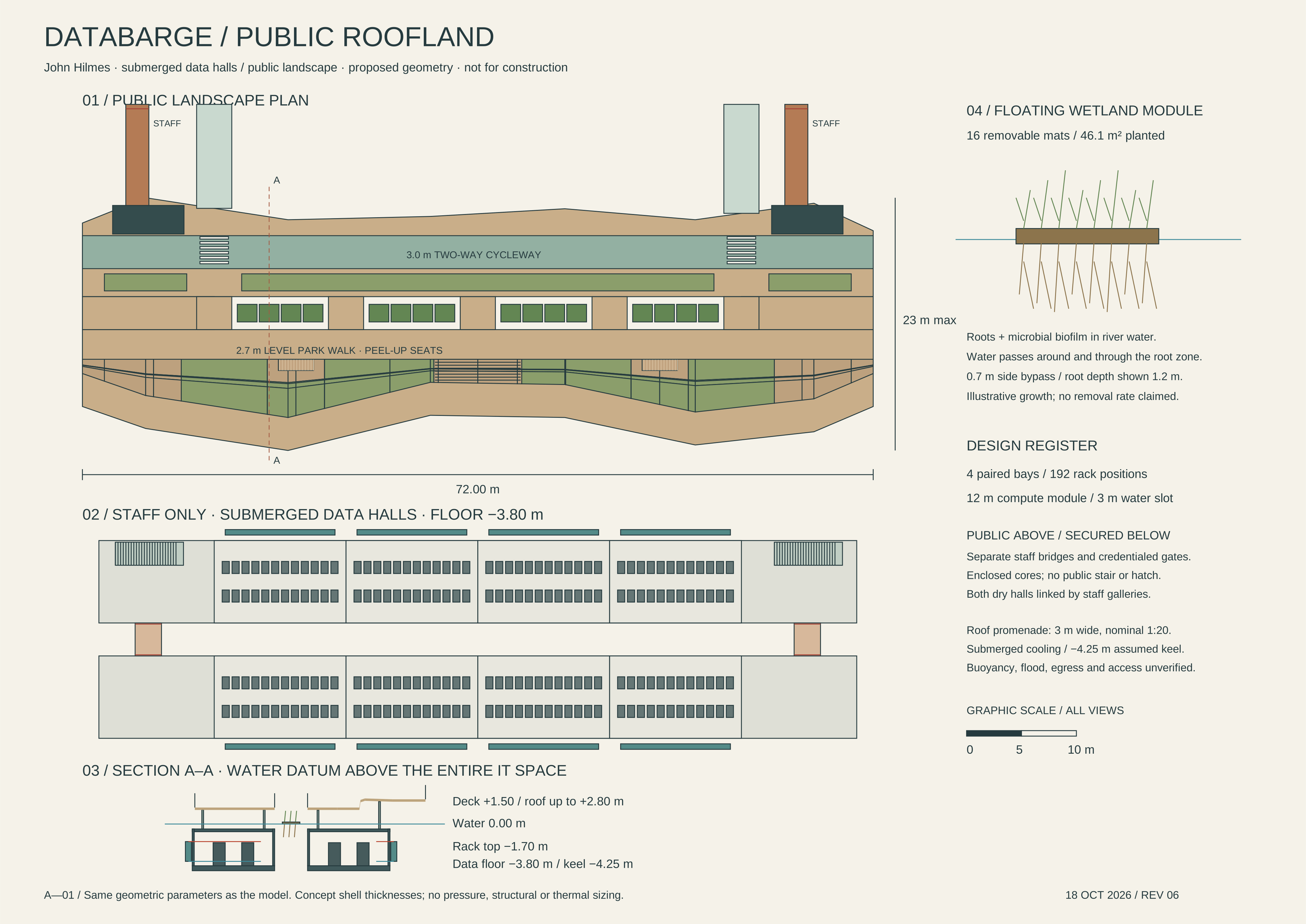
Model coordinates use metres, X along the barge, Y up, Z across the water. GLB export is an assembled model regardless of the current exploded or section view. The SVG sheet is generated from the same dimensional parameters, with furniture simplified.